

IEC Standard MNS Switchgear Explained for Power System Engineers
2026-11-16
IEC MNS switchgear is more than a row of metal compartments—it's a design framework that separates a forgiving assembly from a field nightmare when a fault hits. If you're a power system engineer tired of vague catalog claims, this guide walks through what the standard actually demands: busbar segregation, withdrawable unit mechanics, internal arc ratings, and the details that decide whether your lineup survives a short circuit. We'll also show where MOLDVOLT fits into that picture, especially when standard options fall short.
Why the MNS Designation Still Matters in IEC Low-Voltage Assemblies
In a market flooded with generic low-voltage switchgear, the MNS designation carries weight for a simple reason: it signals a specific, proven engineering lineage rather than a mere assembly of breakers and busbars. Engineers and panel builders who specify MNS know they are referencing a system with defined mechanical constraints, busbar ratings, and a modular design that has been refined over decades. That predictability reduces design review cycles and commissioning surprises, especially when a plant’s layout demands high packing density without compromising thermal performance.
The continued relevance of MNS also stems from how it shapes maintenance and expansion habits. Unlike custom-built assemblies that often require vendor-specific training or specialized tools, MNS-style systems tend to use standardized withdrawable units and form separation that field technicians recognize across different projects. This familiarity lowers the cost of ownership long after the initial installation, and it allows owners to add feeders or reconfigure panels without a full redesign. In aging industrial facilities where original drawings are lost or incomplete, the MNS label gives operators a reasonable starting point for retrofits and spare parts sourcing.
Yet the designation persists not because it is frozen in time, but because it adapts while keeping core interfaces stable. Modern MNS-derived assemblies incorporate arc-resistant features, intelligent motor control, and higher short-circuit withstand ratings without breaking compatibility with older footprints. That balance between innovation and backward compatibility is rare in electrical infrastructure, where a radical change often means expensive demolition and rewiring. For consultants and asset managers who must justify every capital expense, choosing a panel with the MNS heritage is often the defensible middle path between unproven custom designs and legacy gear nearing end of life.
Form Segregation in MNS Panels: Reading Between the Partition Lines
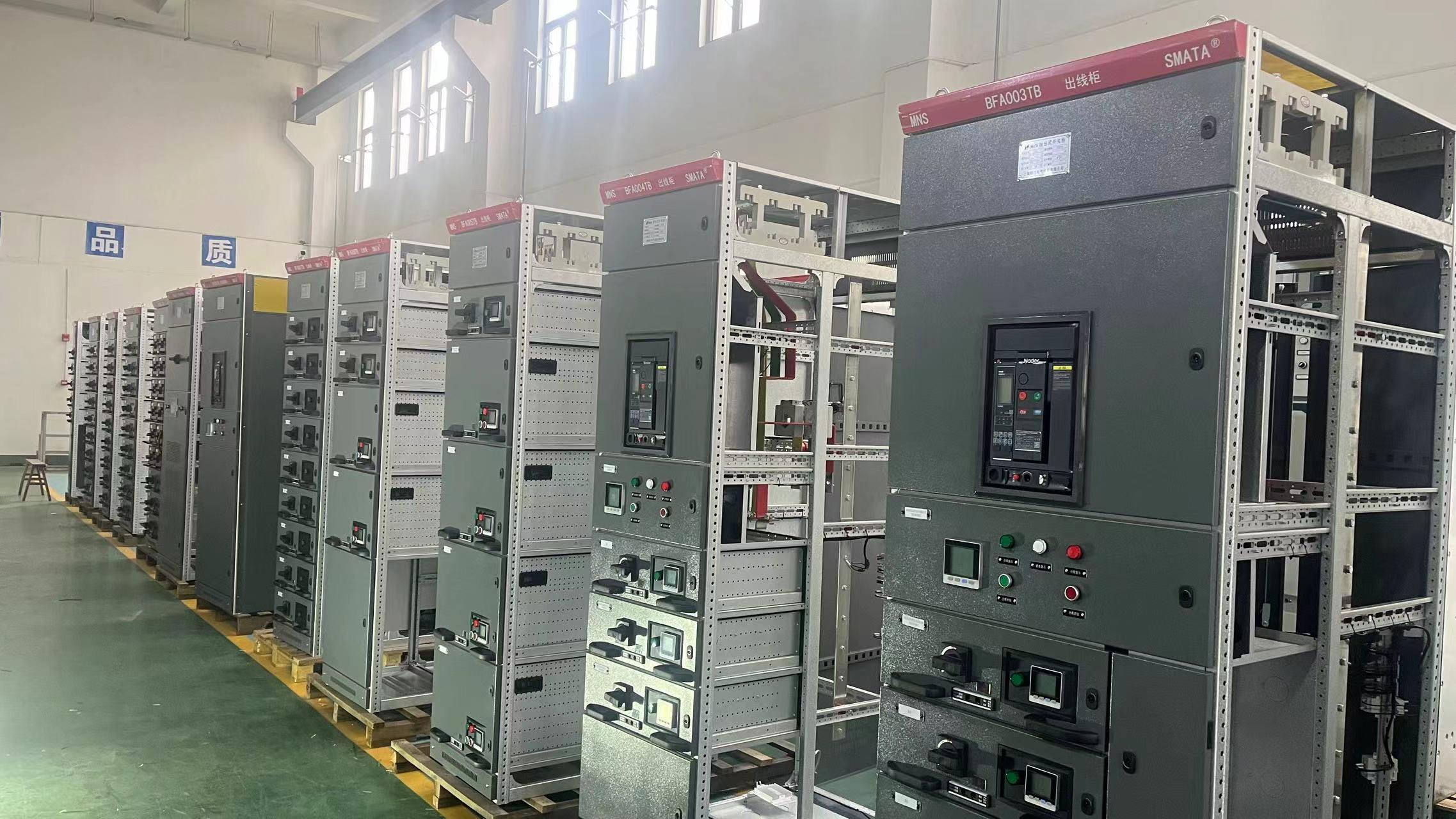
On a single-line diagram, form segregation in MNS panels often looks like a set of tidy boxes separated by bold lines. But those lines rarely tell you whether a cable termination shares the same compartment as a neighboring functional unit, or whether the busbar zone can be accessed without exposing live parts from an adjacent section. In practice, the space between partition lines is where maintenance risk, fault containment, and operational flexibility are actually decided.
A common reading error is to assume that higher form numbers are automatically safer or more practical. For example, Form 3b keeps busbars separate from all functional units and provides separation for cable terminations, which may be enough if maintenance is limited to individual outgoing circuits. Form 4b adds separation between terminals of different units, but that extra metalwork also reduces usable space and can complicate cable routing. The choice should follow the actual switching and isolation procedures used on site, not just a preference for more compartments.
Reading between the partition lines also means checking what the barriers are made of and how they are fixed. Metallic partitions provide better fault containment but can create eddy current heating if not properly bonded, while insulating barriers may be easier to retrofit but offer less mechanical protection. The difference becomes visible only when a panel is opened for inspection — which is exactly when the segregation strategy is tested.
IEC 61439 Verification for MNS: Beyond the Type-Test Label
The type-test label on MNS assemblies often reads as a final verdict, but IEC 61439 replaces that notion with a broader requirement for verified design. A single test certificate cannot cover every busbar arrangement, device mix, or enclosure variant that leaves the workshop. Under the standard, compliance must be demonstrated for each unique assembly configuration through testing, calculation, or adherence to established design rules. For MNS, this means the base platform may pass a severe short-circuit or temperature-rise test, yet a customer-specific panel with different internal separation or reduced ventilation needs its own documented verification before it can claim conformity.
The strength of the MNS system lies in how it supports derivation from reference designs. Rather than re-testing every panel from scratch, engineers compare the new configuration against a tested or calculated baseline, confirming that changes in conductor sizes, device placement, or compartment geometry stay within defined boundaries. This comparative verification is not a rubber stamp; it requires traceable records of clearance and creepage distances, temperature-rise calculations, and short-circuit withstand assessments. When the differences exceed what the reference design allows, additional tests or refined calculations become unavoidable. That discipline separates genuine verified performance from a label applied by habit.
Routine verification adds another layer that the label cannot replace. Each completed MNS assembly still needs inspection and testing to confirm correct wiring, dielectric integrity, and the operation of protective measures after transport and final installation. These checks catch assembly errors and material substitutions that design verification alone would miss. A meaningful compliance package therefore includes both the design verification file and the routine test report, not just a nameplate or certificate hanging on the door.
Thermal Limits and Busbar Sizing in MNS: What Nameplate Ratings Leave Out
Nameplate current ratings assume a narrow set of reference conditions—typically 35°C ambient, open-air test setups, and specific enclosure sizes. Inside an MNS assembly, those assumptions break down quickly. Busbars are crowded into compartments, heat from adjacent breakers and cable connections accumulates, and natural convection is restricted by IP-rated panels. As a result, a bar that passes a type-test on its own can run dangerously hot once installed, even if the line current stays below the label value.
Busbar sizing decisions often start and end with ampacity tables, which is where many designs go wrong. Those tables ignore the thermal coupling between parallel conductors, the added resistance from poor joints, and the derating effects of harmonic loads. In an MNS cabinet, vertical and horizontal busbar runs experience different airflow patterns; vertical sections may benefit from chimney-effect cooling, while horizontal bars at the top can trap heat. Reducing cross-section to save copper may still satisfy a spreadsheet calculation, but it could push insulation temperatures beyond long-term aging limits. The result is not sudden failure, but accelerated degradation of supports, coatings, and nearby cable insulation.
A more realistic approach treats the switchboard as a thermal system, not a collection of individually rated components. This means verifying temperature rise at the hottest points—joints, bends, and areas near ventilation dead zones—under the actual enclosure class and fill factor. It also means accounting for future load growth and the presence of non-linear loads that increase eddy-current losses. In many retrofits, replacing a busbar with a larger section or adding forced ventilation is cheaper than repairing heat-related damage after a few years of operation. The nameplate only tells you what the busbar can handle on a test bench; the cabinet layout, connection quality, and real operating environment decide whether that number means anything inside the MNS.
Positioning MNS Gear in Power Networks Without Redundant Overdesign
Selecting the right MNS gear for a power network is rarely about chasing the highest possible ratings. It is about understanding the actual load profile, fault current availability, and operational headroom needed for realistic expansion. Many installations end up with switchgear that is technically compliant but financially and spatially wasteful because the specification process defaults to conservative multipliers at every step. The first step in avoiding this is to stop treating the gear as a standalone component and instead map its role within the wider protection and coordination scheme. When the upstream transformer impedance, cable lengths, and downstream motor starting currents are known with reasonable accuracy, the required breaking capacity and thermal withstand can be matched far more tightly than a generic 125 percent rule would suggest.
A practical approach starts with a granular load census rather than an aggregate connected load figure. Demand factors, diversity across feeders, and expected duty cycles rarely align with nameplate totals. By modeling the network with actual time-current curves and considering both normal and contingency switching states, it becomes possible to specify busbar ratings and circuit breaker frame sizes that handle genuine worst-case scenarios without adding unused ampere capacity. This also means reviewing whether the gear will ever be required to parallel transformers or motors in a way that changes short-circuit contribution. If such operating modes are prohibited by interlocking or operating procedures, there is no reason to design for them.
The final piece is to challenge fixed safety margins that have accumulated over years of standard practice. A ten percent margin on top of a calculated fault level that already includes motor contribution and a conservative source impedance is not redundancy; it is overdesign. Working closely with protection engineers to set realistic relay pickup and time delays can allow a lower interrupting rating while still providing selective coordination. Similarly, choosing modular MNS designs that allow future addition of busbar sections or replacement of breakers with higher ratings only when actually needed can eliminate upfront oversizing. This strategy keeps capital cost, footprint, and lifetime maintenance aligned with the network’s true demands instead of an imagined worst case that never materializes.
Commissioning, Expansion, and Retrofit: MNS Lessons From the Field
Bringing a motor control center online for the first time often exposes gaps that drawings never reveal. During a recent commissioning, we found that the field wiring labels did not match the updated single-line, which forced a late-night re-verification of every bucket. The takeaway was simple: walk down the entire lineup with the as-built schematics in hand before any power is applied, and double-check that the control transformer taps are set for the actual available voltage.
Expanding an existing MNS section seems straightforward until you realize the original busbar sizing left no headroom for additional large starters. Instead of forcing a new feeder into a crowded vertical section, we split the added loads between two columns and used a spare compartment to house a small PLC for sequencing. Retrofitting older buckets with new electronic overload relays also required adapting the door-mounted reset buttons, since the physical travel differs from the old thermal units.
The biggest lesson from retrofit work is that documentation decays faster than hardware. Keep a log of every field modification—torque marks, wire numbers, and revised settings—directly on the inside of the bucket door. This habit saves hours during the next shutdown and prevents the classic mistake of assuming the drawings still reflect reality.
FAQ
MNS is a low-voltage withdrawable switchgear and motor control center system built around a modular, compartmentalized steel frame. It falls under IEC 61439-1/-2, meaning every assembly must be verified by type tests, design checks, or a combination of both rather than relying solely on individual component ratings.
The main difference lies in its withdrawable functional units and busbar segregation. Instead of hardwired breakers in a single open compartment, MNS uses plug-in modules that can be isolated, exchanged, or upgraded without killing the entire bus. This reduces outage time and simplifies fault containment.
MNS panels can be built to Forms 1 through 4 as defined in IEC 61439-2, with Form 4 being the most common for critical processes. Higher forms physically separate busbars, terminals, and functional units, so a fault in one drawer is far less likely to cascade into adjacent circuits. Engineers often specify Form 3b or 4b to balance maintenance access against operational safety.
Standard MNS designs are routinely verified for 50 kA or 65 kA for one second, and higher ratings up to 100 kA are possible with reinforced busbar supports and bracing. The exact figure depends on the busbar layout, copper cross-section, and the type-tested combination of incoming and outgoing circuits. Always request the manufacturer's verification report rather than assuming a catalogue value.
Yes, a single MNS run can mix incoming feeders, bus couplers, motor starters, variable speed drive cubicles, and capacitor banks. The modular frame and standard busbar positions let designers allocate compartments according to load type without splitting the switchgear into separate boards. This keeps the footprint small and simplifies cable entry planning.
Each functional unit can be racked to a test or isolated position while the main bus remains live, so maintenance tasks are performed without a full plant shutdown. The units have mechanical interlocks that prevent insertion or withdrawal under load, and shutters cover live contacts when a drawer is removed. That reduces both arc-flash exposure and the temptation to bypass safety procedures.
Under IEC 61439-2, the manufacturer must provide a declaration of conformity and the specific verification method used for each design item—type test, design rule, or routine test. Request the full verification dossier, including temperature-rise tests, short-circuit test reports, dielectric test results, and IP rating certification for the exact enclosure configuration you are buying.
One frequent mistake is not defining the ambient temperature, humidity, or altitude at the installation site, which can derate the busbars and electronic components. Another is specifying a Form number without clarifying how many barriers are actually required around cable compartments and busbar joints. Finally, failing to state the expected harmonic load can lead to undersized neutral conductors in four-pole configurations.
Conclusion
The MNS label survives in IEC low-voltage assemblies not as a legacy badge but because it frames how engineers specify and verify performance under IEC 61439. A panel carrying this designation still implies a disciplined approach to form segregation, where partition arrangements between busbars, terminals, and functional units dictate both safety during live work and the ease of isolating faults. Reading between the partition lines matters: Form 3b or 4b choices change cable access, arc containment, and maintenance windows, so the engineer who treats the form number as a checkbox often discovers later that the panel cannot be serviced the way the site procedures demand. Verification under IEC 61439 adds another layer that a type-test label alone cannot cover. Routine and design verification must account for the actual assembly, not a reference design, forcing attention to temperature-rise limits, dielectric properties, and short-circuit withstand for the specific busbar arrangement and enclosure.
Thermal limits expose what nameplate ratings leave out. Rated current is only meaningful when the enclosure, IP rating, ambient temperature, and internal separation are known; a 2500 A busbar in a tightly compartmented Form 4 panel may behave very differently from the same rating in open air. Busbar sizing therefore needs derating checks for hotspots, ventilation, and parallel conductor sharing, especially where non-linear loads or harmonic currents are present. Positioning MNS gear in a power network calls for the same restraint: engineers often overdesign by stacking safety margins on top of safety margins, ending up with larger transformers, oversized cables, and unnecessary cost without any reliability gain. Field experience from commissioning, expansion, and retrofit reinforces that documentation, spare capacity, and physical clearance decide long-term performance more than a conservative short-circuit rating. Retrofits succeed when the original form segregation and busbar layout were recorded honestly, allowing new feeders to be added without compromising verified clearances or creating undocumented thermal bottlenecks.
Contact Us
Contact Person: Hellen
Email: [email protected]
Tel/WhatsApp: 86-13634205622
Website: https://www.voltcabinet.com