

Multi Core Fiber Fusion Splicer Manufacturer Selection Guide for High Density Fiber Deployments
2026-08-17
High-density fiber deployments are pushing multi-core fiber into the spotlight, but the real bottleneck often hides in the splicing trailer. A fusion splicer that handles single-core without issues can fall apart when alignment tolerances tighten across multiple cores. This guide cuts through the usual spec-sheet noise to examine what actually matters when selecting a multi-core fusion splicer manufacturer for high-density builds. As you evaluate options, pay close attention to how DVP addresses field repeatability and core alignment—it might reshape your shortlist.
Where High Fiber Counts Expose Splicer Weaknesses
When a ribbon cable holds twelve or twenty-four fibers, a minor alignment drift of half a micron stays invisible; splice loss remains comfortably low. Push that count to 200 or 400 fibers in a single tray, and the same physical drift translates into cumulative insertion loss, reflectance spikes, and occasional fiber breaks at the clamp edges. High-count splicing turns the splicer's core geometry estimation from a routine check into a fragile prediction — small inconsistencies in V-groove wear, electrode tip erosion, or even dust on the lens now propagate across the entire array, and the machine's self-calibration often lags behind the real-time degradation.
Thermal management quietly becomes another weak point. A standard splicer's heating oven may handle a single 12-fiber ribbon without issue, but when you process dozens of high-fiber-count ribbons back to back, the oven's temperature profile shifts. The outer fibers reach the shrink tube's glass transition temperature faster than the inner ones, causing uneven sleeve shrinkage and micro-bends that only appear during OTDR testing days later. Electrode life also drops sharply: dense fiber arrays force the arc to work harder to achieve uniform fusion, which accelerates electrode pitting, and many operators discover that a splicer rated for 5,000 splices needs electrode replacement after barely 1,200 high-count splices.
Software limitations surface too. Most splicers optimize their motor movements for a typical 12- or 24-fiber ribbon; when you feed in a 200-fiber bundle or a stack of loose tubes, the auto-focus routine hunts longer, occasionally locking onto a neighboring fiber's cladding instead of the core. Estimated splice loss values become unreliable — the machine reports 0.02 dB while the real loss exceeds 0.15 dB on one or two fibers. And because high-count work is often done in tight splice enclosures, the splicer's physical footprint and the angle of its fiber holders can force unnatural routing, adding stress that no software correction can undo.
Core Alignment Claims vs. What the OTDR Sees Later
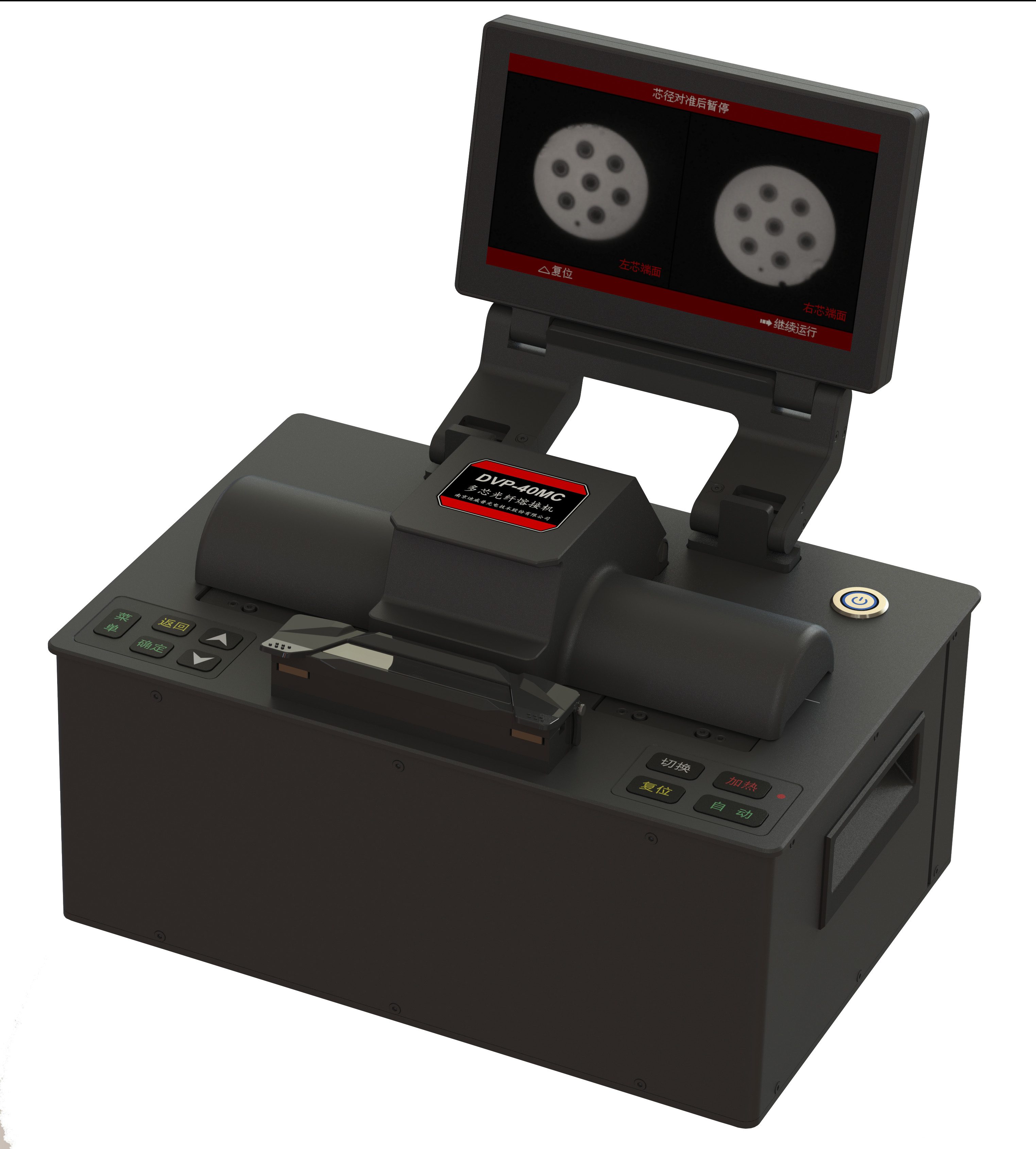
Splicer datasheets love to boast about core alignment precision down to a tenth of a micron. Technicians often take those numbers at face value, assuming every splice will land perfectly centered. But the OTDR has a habit of telling a messier story. A fusion set can report a clean alignment on its screen while the actual fiber geometry — slight ovality, a bit of dust, or a barely perceptible cleave angle — quietly undermines the result.
Once the splice is buried in a closure or strung across a span, the OTDR trace becomes the only honest witness. It doesn't care about laboratory conditions or marketing brochures. The backscatter signature might show a small reflective peak where the alignment supposedly matched perfectly. Or worse, a non-reflective event with higher loss than expected, hinting at a core offset that the splicer's camera never flagged. Those discrepancies accumulate over a route and turn a pristine test report into a troubleshooting headache.
The gap between claimed alignment and OTDR reality isn't always dramatic — often a few hundredths of a dB here and there. But multiply that across dozens of splices and the total loss can silently eat into your power budget. Experienced techs learn to trust the trace more than the splicer's self-assessment. They also learn that a perfect core alignment on paper means little if the fiber coating wasn't stripped cleanly or the heat shrink slid slightly during the shrink cycle.
Cladding Diameter Tolerance and the Reality of 250µm Coated Fiber
Manufacturers quote a cladding diameter of 125 µm with a tolerance of ±0.7 µm, but that number hides more than it reveals. In production, the glass is drawn from a preform and measured on-line; drift in furnace temperature or draw speed can push the cladding out to 125.5 µm or down to 124.6 µm without breaching the spec. What matters for splicing and connectorization is not just the average, but the short-range variation along a reel. A 0.5 µm step over a few meters can create a lateral offset that eats into alignment budget before the fiber even reaches a ferrule.
The 250 µm coated fiber adds another layer of real-world fuzziness. The coating diameter is typically held to ±10 µm or tighter, but concentricity between the glass cladding and the UV-cured acrylate is the silent variable. When the coating is applied slightly off-center, the 250 µm outer surface no longer shares an axis with the 125 µm cladding. Connector ferrules grip the coating, so any eccentricity translates directly into core offset at the mating interface. Field installers see this as inconsistent insertion loss across supposedly identical connectors.
Testing under a microscope with a calibrated micrometer often tells a different story from the datasheet. A batch of 250 µm coated fiber may show cladding diameters ranging from 124.8 to 125.4 µm and coating diameters from 247 to 253 µm. These variations are within most industry specs but become visible when splicing dissimilar fibers or using tight-tolerance mechanical splices. Field teams quickly learn to measure a few meters from each reel before committing to a high-count ribbon splice or a low-loss connector assembly.
Splicing Software That Keeps Up With Dense Cable Routing
Modern fiber optic networks are pushing cable densities to levels that would have seemed impractical just a few years ago. In congested splice enclosures and high-fiber-count trunks, the margin for error shrinks with every additional buffer tube. Splicing software built for this reality does more than log splices—it actively interprets the routing geometry, tracks fiber positions across trays, and flags potential conflicts before the first heat shrink goes on. The result is a workflow where the software keeps pace with the physical complexity, rather than forcing technicians to simplify their routing just to match the tool.
A key differentiator is how the software handles non-linear routing paths. Instead of assuming every fiber follows a neat, sequential path from tray to tray, it models actual cable entry points, slack loops, and mid-span access. This allows the splice plan to reflect what the technician sees in the enclosure, not a idealized diagram. When a route doubles back or crosses an already occupied tray, the software recalculates remaining capacity and suggests alternative layouts. That level of spatial awareness reduces rework and prevents the kind of last-minute tray swaps that slow down large deployments.
What sets leading tools apart is their ability to learn from dense routing patterns. By analyzing past projects, the software can pre-seed splice plans for similar cable types and enclosure models, cutting down planning time significantly. Technicians working on high-count splices benefit from intuitive visual cues—color-coded tray occupancy, predicted bundle diameters, and real-time warnings when a proposed path exceeds bend radius limits. These features don't replace skilled hands, but they remove the guesswork that accumulates when dozens of fibers compete for the same space.
The Hidden Costs of Calibration, Electrodes, and Downtime
Calibration is often seen as a routine five-minute task, but the real cost quickly adds up. Each cycle consumes certified buffer solutions, cleaning reagents, and technician time that could be spent on actual measurements. For facilities running multiple sensors around the clock, that can mean hundreds of hours per year lost to repetitive maintenance rather than productive analysis.
Electrodes are not a one-time purchase. Depending on the process conditions, a pH or ORP electrode may need replacement every few months, and improper storage or cleaning only shortens that interval. The hidden expense isn’t just the price of the electrode itself—it’s the cumulative cost of stocking spares, reordering at the last minute, and dealing with drift or sluggish response before anyone realizes the probe is failing.
Every calibration or electrode swap means the sensor is offline, and in continuous processes that downtime is rarely free. A delayed pH reading can hold up a neutralization step, a fermentation batch, or a water discharge permit. Over a year, the minutes stolen by maintenance often translate into missed production targets or compliance risks that no one budgets for upfront.
Field Repairs in Tight Enclosures: What Manufacturers Don't Show at Demos
Pop open an access panel on a machine that's been wedged between a concrete column and a cable tray, and the demo-floor polish disappears. What looked like a tidy row of DIN-rail terminals now sits behind a strut you can't remove without dropping the neighboring conveyor's guard. You're on your knees, one arm twisted past a filter housing, trying to reach a fastener that the CAD model never flagged as obstructed. Torque specs assume a straight shot with a calibrated driver; in the field, you're using a cut-down Allen key ground to half its length and praying the ball end doesn't strip.
The real headache isn't the component failure itself—it's the sequence of small disassemblies required to get to it. Manufacturers film demos with panels off and harnesses pre-routed, but nobody shows the hour spent unclipping six zip ties, removing a bracket that holds nothing but air, and easing a rigid conduit out of the way just to see the back of a power supply. Clearance numbers on a spec sheet don't account for swollen gaskets, added cable slack, or a safety relay mounted exactly where your knuckles need to go. By the second repair, techs stop trusting the intended access points and start cutting openings in enclosures that were never designed to be cut.
Worse, tight enclosures punish improvisation. A replacement board slips in at a slight angle and shears a capacitor against the door frame. An inline connector gets replaced with a field-wired terminal strip because there's no room for the proper tool. Heat becomes a silent second fault: the same cramped space that blocks your hand also blocks airflow, so the new part fails months later for reasons that get blamed on component quality instead of packaging. Until manufacturers include a realistic human arm and a service loop in their digital mock-ups, field technicians will keep learning the hard way—one scraped knuckle at a time.
FAQ
A dependable unit handles multiple cores in one alignment and splicing cycle without sacrificing loss performance. Look for automated core-to-core alignment that adapts to slight pitch variations between fibers, plus stable clamping for ribbonized or bundled multi-core cables. The real differentiator shows up during repeated use in cramped splice trays where rework is costly.
Field support and firmware update cadence often outweigh small spec differences. Choose a manufacturer that publishes real attenuation data per core position, offers re-calibration services near your deployment regions, and has splicers already validated by crews doing similar high-count trunk or edge builds.
Run a short trial with the actual cable type you will deploy. Splice at least 20 consecutive joints, record per-core loss, and check the spread between best and worst core. Tight spread under varying temperature and modest dust exposure tells you more than a single lab number.
Electrode geometry and cleaning access determine how long a splicer stays stable during a full day of high-count work. Models with wider electrode spacing and self-diagnostic arc checks reduce the need to interrupt splicing for manual re-optimization, which matters when every tray has dozens of cores.
Different multi-core cable designs use different coatings and core spacing. If a splicer forces you into proprietary holders for each cable type, the logistics burden grows quickly. Ask whether the manufacturer supports adjustable or universal holders that maintain alignment without adding fragile adapters.
The interface should let technicians save per-cable recipes that include core count, pitch, and arc power. Avoid systems that reset settings after firmware updates or hide advanced calibration behind service passwords. Fast recipe recall reduces mistakes during overnight maintenance windows.
It is critical because re-splicing even one core in a dense cable can disturb neighboring splices. Look for sealed wind protectors, hydrophobic touch surfaces, and easy-to-replace mirrors. Splicers that tolerate sawdust, concrete dust, or high humidity without frequent recalibration keep crews moving.
When your deployment schedule has little room for rework and the fiber count per closure is high. The extra cost returns through fewer abandoned splices, less technician fatigue, and the ability to hand the same machine to a less experienced crew member without a spike in failure rate.
Conclusion
In high-density fiber deployments, a multi-core fusion splicer is only as good as its performance when every fiber in a bundle demands consistent loss. Standard splicers often fall apart once tray routing gets tight and fiber counts climb past a few hundred strands. The first place this shows is in core alignment claims. A manufacturer can demonstrate a perfect splice on a clean bench setup, but later an OTDR trace on a live route reveals small offsets from bent or stressed 250µm coated fibers that the alignment camera never caught. That difference between bench specs and field reality is exactly where many units fail. Cladding diameter tolerance compounds the issue: coated fiber from different vendors or older cable stock often sits near the edge of the nominal 250µm envelope, and if the splicer's V-grooves or clamps do not handle that variation gracefully, the core alignment calculation drifts. Splicing software matters just as much. Dense cable routing means the technician is working through tight loops, buffer tubes, and mid-span access, so the splicer must not force a rigid, slow workflow. Software that re-runs calibration or resets estimates after each splice will add hours to a large-count job.
The hidden costs are less obvious during a demo. Calibration cycles, electrode replacement frequency, and the downtime waiting for both can quietly erase the savings from a cheaper unit. A splicer that needs electrode cleaning every 50 splices or drifts out of calibration when moved between climate-controlled trailers and hot vaults becomes a liability on a high-count deployment. Field repairs in tight enclosures are another area where demo performance misleads. On a show floor, the splicer sits open and accessible; inside a crowded fiber dome or a handhole with limited slack, getting the fiber into the unit and closing the windshield without disturbing the splice is a different skill. Manufacturers rarely show this because it exposes how the ergonomics, clamp design, and even the placement of the heating oven work against the technician. Choosing a multi-core fusion splicer for dense builds means testing the unit under those exact conditions: with real 250µm coated fiber from your own inventory, in a mock enclosure, and with an OTDR verification after a full tray of splices.
Contact Us
Contact Person: Mr XU
Email: [email protected]
Tel/WhatsApp: 86-25-85582828
Website: https://www.dvp.cn/en/