

OEM Cast Parts Quality Standards Every Manufacturer Should Know
2026-09-27
In the world of OEM manufacturing, cast parts often make or break your final product—yet their quality standards are too frequently left to chance. From dimensional accuracy to material integrity, every overlooked detail can lead to costly rework or field failures. At Zhaoyuqi, we’ve seen how clear, enforceable standards separate reliable supply chains from constant firefighting. This guide breaks down the essential quality benchmarks every manufacturer should understand before accepting their next shipment.
What a Mill Certificate Actually Tells You—and What It Doesn’t
A mill certificate—or MTR—gives you the chemical makeup and mechanical test results from one heat of metal. The lab numbers for yield strength, tensile strength, elongation, and composition were pulled from test coupons, not from every square inch of the order. So the certificate tells you that the sampled material met a standard like ASTM A36 or 316L. It does not tell you that all 12,000 pounds share those exact values.
The untold part is often more relevant to your job. The certificate won't mention centerline segregation, inclusions, or hard spots that developed during cooling. It won't warn you about how the material will react to your plasma cutter settings, your welding wire, or your heat treatment cycle. Those variables are yours, and the mill has no data on them.
Also absent are the trace elements and properties that the standard skipped. If hydrogen-induced cracking, low-temperature toughness, or machinability matter in your shop, a basic mill cert won't answer those questions. You might need a supplementary test report, a corrosion coupon, or at minimum a conversation with the mill's technical desk. A certificate proves a sample passed; it doesn't prove your part will.
Dimensional Checks That Prevent Machining Surprises
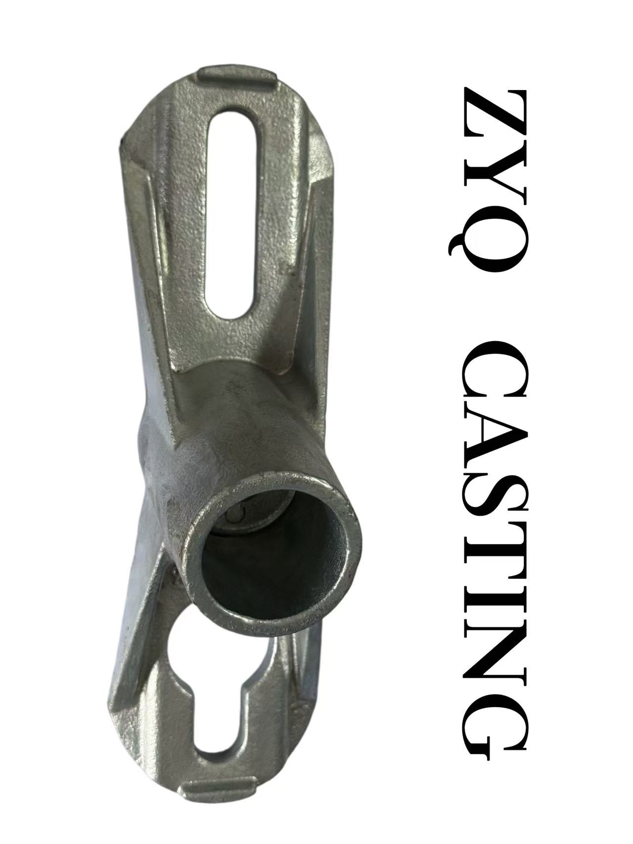
Machining drawings carry tolerances that look harmless on screen but turn into scrap metal if you skip the dimensional checks. A quick pass with calipers or a height gauge before the cutter touches the part catches stock oversize, misplaced datums, and fixture shift that no CAM simulation will flag. The habit of measuring raw material thickness, locating hole positions from a verified edge, and confirming the vise is trammed in saves you from discovering a 0.5 mm error only after three setups are done.
The real trick is checking the right dimension at the right time. Instead of verifying every feature at the end, split the job into trigger points: after facing, after roughing, and before any finishing pass. At each stage, compare the actual measured value against the nominal plus the remaining stock allowance. If a bore is already 0.2 mm under final size before the finish pass, you know the tool wear or deflection is eating your margin. That early warning lets you adjust speeds, offsets, or even re-order material before the part becomes a paperweight.
Another layer that prevents surprises is cross-checking dimensions that should agree with each other. Wall thickness, for example, is not just a single caliper reading; it is also the outside dimension minus the bore diameter divided by two. When those two numbers disagree by more than your measuring uncertainty, something is off: a shifted zero, a bent boring bar, or a part that moved in the fixture. Catching that mismatch before unclamping lets you correct course while the part is still located, turning a potential scrap event into a minor offset tweak.
Surface Quality: Reading the Cast Skin for Root Causes
Observing a casting's outer skin can reveal a surprising amount about what went wrong inside the mold. Take the small, scattered pits that often appear on the surface—they rarely stem from a single cause. A foundry engineer will first run a fingertip across the area to feel how easily sand grains detach, then use a magnifier to distinguish between sand erosion and incomplete metal fill. Often the real culprit is a combination of low sand compaction and a pouring temperature that dropped just below the sweet spot.
Gas-related surface defects tell another story. Smooth, rounded cavities with no obvious pattern typically point to poor venting or excessive moisture in the molding sand. If those cavities cluster near the sprue or in thick sections, it's worth questioning whether the gating system introduced more air than the metal could expel, or whether the alloy simply ran out of time to let bubbles rise before the skin froze over.
Surface cracks demand the most careful reading. Hot tears follow grain boundaries and show an oxidized, discolored edge, signaling that the alloy was still mushy when shrinkage stresses exceeded its strength. Cold cracks, by contrast, have cleaner fracture faces and usually appear during shakeout or fettling. By tracing the crack path and noting the degree of surface oxidation, you can often pinpoint where residual stress concentrated during cooling—and then adjust the riser placement or improve the mold's collapsibility to prevent a repeat.
The Hidden Flaw Problem: NDT Methods Worth Specifying
Surface-level checks miss the flaws that actually bring components down. A casting can look perfect while internal porosity, lack of fusion, or stress-corrosion cracks quietly eat away at load-bearing integrity. This is why specifying the right nondestructive testing method up front matters more than adding another inspection step later. Ultrasonic testing and radiography earn their place when you need volumetric data, but they are not interchangeable: UT catches planar defects that radiography can miss, while radiography gives a permanent density map that often reveals inclusions or shrinkage before they become arguments between supplier and buyer.
For near-surface and surface-breaking flaws, eddy current and magnetic particle methods do the heavy lifting. Eddy current works well on conductive materials where paint or coatings would hide cracks from visual inspection, and it can be tuned to ignore harmless geometry changes. Magnetic particle remains the fastest way to find fine fatigue cracks in ferritic steel, but it only earns that speed if the specification calls for the right current type, field direction, and particle contrast. Skipping those details often means a clean report and a hidden flaw that nobody tested for.
Heat Treat Verification: Hardness, Microstructure, and Real Evidence
When a batch of parts comes back from heat treatment, the first thing most shops reach for is a hardness tester. But hardness alone tells a dangerously incomplete story. A part can sit right in the middle of the Rockwell C specification and still fail in service because the microstructure is all wrong. That is why verification has to go beyond a quick surface check and look at what actually happened inside the metal.
Cutting a coupon, mounting it, and attacking it with abrasive papers and etchants reveals the real evidence. The grain boundaries, phase distributions, and any signs of decarburization or retained austenite show up under the microscope. A properly normalized or quenched-and-tempered structure has a certain look, and experienced eyes can spot shortcuts the furnace operator hoped nobody would notice. Photos of these microstructures become the proof that the process was controlled, not just lucky.
Real evidence also means connecting the lab results to the actual part geometry and service conditions. A test block that passes hardness is not the same as a thin-walled boss or a sharp corner on a real component. Verification should include sectioning a sacrificial part from the production run, checking hardness at multiple depths, and documenting the transformation with images that anyone can review later. That combination of measured hardness, clear microstructure, and physical samples is what separates a trustworthy heat treat from a guess.
Auditing the Foundry’s Process Before You Cut a Purchase Order
Placing an order without walking the foundry floor is like buying a car based on a photo of the steering wheel. You need to see the pour, the shakeout, the grind room — not just the sample parts on the conference table. Ask to audit a live run of your actual casting, not a demo job they’ve done a hundred times. Watch how they handle pattern changes, core setting, and any rework loops. A foundry that hesitates or hides parts of the process is already telling you what the first article will look like six weeks late.
Don’t confuse a clean office with a controlled process. You want to see control plans that match the actual work instructions pinned at each station — not a binder full of generic procedures. Check whether operators record data because it matters or because an auditor once told them to. Look at the scrap bin: if it’s overflowing with the same defect day after day, that’s a culture problem, not a one-off mistake. Ask about their corrective action log and see if the fixes are permanent or just band-aids until the next shipment.
Finally, talk to the people who touch your parts, not just the sales engineer. The grinder who has to blend an extra quarter inch off every cope side knows more about the pattern than the CAD file ever will. If the foundry won’t let you speak to the floor staff, walk away. A purchase order signed after a real process audit gives you leverage when things go wrong — and in casting, something always goes wrong, so you might as well know which failures you’re buying into before you pay for them.
FAQ
Beyond the drawing, it comes down to three things: material integrity, dimensional accuracy, and surface condition. A foundry must prove the alloy matches the spec with a certified heat number, demonstrate that key dimensions fall within the agreed tolerance band, and show that surface defects won't compromise function or coating adhesion.
Ask for a material certificate that includes chemical composition and mechanical test results from a sample cast in the same lot. For high-stress parts, request tensile, hardness, or impact testing, and cross-check against the applicable ASTM, ISO, or EN standard. Don't accept a generic cert that doesn't trace back to the actual heat or batch.
Sand casting typically holds ±0.03 inch for small features and more for larger ones, while investment casting can achieve ±0.005 inch per inch or better. The key is to agree on a tolerance standard like ISO 8062 or ISO 2768 before production, because 'tight enough' means different things to different foundries.
Not automatically. The decision depends on location, depth, and whether the defect will be machined away or exposed to stress. A pit in a non-critical cosmetic area might be acceptable if it's below the agreed maximum size, but the same pit near a seal surface or threaded hole is a reject. Use visual acceptance criteria like MSS-SP-55 or a custom boundary sample.
For internal soundness, radiography and ultrasonic testing are the go-to methods. Magnetic particle and dye penetrant are better for surface and near-surface cracks. The right choice depends on the alloy and the part's failure risk: aluminum and steel castings for pressure or safety applications often need radiographic inspection, while a simple bracket may only need visual and dimensional checks.
Castings can have residual stresses and inconsistent grain structures. Heat treatment normalizes or hardens the material to meet mechanical property targets. A trustworthy foundry records furnace charts for each batch, includes the treatment in the cert, and can show the process complies with a recognized spec like AMS 2770 for aluminum or ASTM A991 for steel.
At minimum, a certificate of conformance, a material test report tied to the heat lot, and dimensional inspection results for the critical features. For regulated or safety-critical parts, add NDT reports, heat treatment charts, and a first article inspection report. The paper trail is what lets you trace a field failure back to a specific pour or process change.
Don't rely on a sample order alone. Audit their process controls for melting, molding, and finishing. Look at their reject and rework rates, how they handle corrective actions, and whether they have in-house lab capability for chemical and mechanical testing. A foundry that can show statistical process control data and has experience with similar alloys and part complexity is far more likely to hold quality over thousands of parts.
Conclusion
Many manufacturers over-rely on a mill certificate, assuming it guarantees casting integrity. In reality, that document confirms chemistry and mechanical properties for a sample heat, but it won't reveal porosity, shrinkage, or dimensional drift specific to your part. Savvy OEMs supplement material certs with targeted dimensional layouts before machining begins, because a casting that passes chemistry can still wreck a CNC setup if a datum surface is off by half a millimeter. Surface appearance matters too: a rough or pitted cast skin isn't just cosmetic—it can signal gas evolution, poor risering, or excessive rework, so reading the skin as a process fingerprint often prevents downstream failures.
Beyond what the eye can see, specifying the right non-destructive testing method is critical. Radiographic or ultrasonic inspection catches internal voids that dye penetrant never will, and manufacturers should match the NDT technique to the failure mode they fear most. Heat treat verification demands more than a hardness sticker; request actual micrographs or at least hardness traverses to confirm through-thickness response, especially for safety-critical castings. Finally, none of this substitutes for auditing the foundry before issuing a purchase order—walk the floor, check pattern storage, melt records, and process controls. Quality is built into the casting long before the first shipment arrives.
Contact Us
Contact Person: Nico Yin
Email: [email protected]
Tel/WhatsApp: 8618561567088
Website: https://www.ductileironparts.com/