

Powder Valve Manufacturer Explains Critical Design Factors for Reliable Flow Control
2026-08-31
Powder handling systems live and die by consistent flow—clogs, bridging, and erratic discharge can quietly sabotage even the most advanced production lines. Yet the root cause often hides in valve design details that go unnoticed until downtime hits. AVM, a powder valve manufacturer with real-world troubleshooting experience, cuts through the noise to explain the critical design factors that make reliable flow control a reality rather than a gamble.
Material Choice Shapes More Than Just Wear Life
Choosing a material is rarely just about picking something that lasts. A stainless steel shaft might survive years in a wet environment, but if it transfers too much heat into a bearing housing, the whole assembly degrades faster. Conversely, a filled nylon gear can absorb shock and run quietly, yet its dimensions shift with humidity. Wear life is only the most obvious outcome—thermal expansion, chemical compatibility, and even electrical conductivity all shift the moment you swap one material for another.
Maintenance teams often see this hidden dimension. A hard-facing alloy may double the time between rebuilds, but it can also make field repairs more difficult because standard machining tools won't cut it. In contrast, a sacrificial bronze bushing wears quickly but is cheap and simple to replace, keeping unscheduled downtime predictable. That trade-off between replacement frequency, spare part cost, and labor effort shapes the real economics far more than a simple lifespan comparison.
There's also a ripple effect on energy and safety. Lighter polymer composites reduce rotating inertia and lower motor loads, yet they can become brittle in cold storage or release fumes if overheated. A ceramic coating eliminates corrosion but changes how a part fails—sudden fracture instead of gradual wear. Every material carries a bundle of secondary behaviors: friction against mating surfaces, response to cleaning chemicals, and how it behaves at end of life. Overlooking these means designing for one metric while silently inheriting several others.
Seal Geometry and the Price of Tiny Gaps
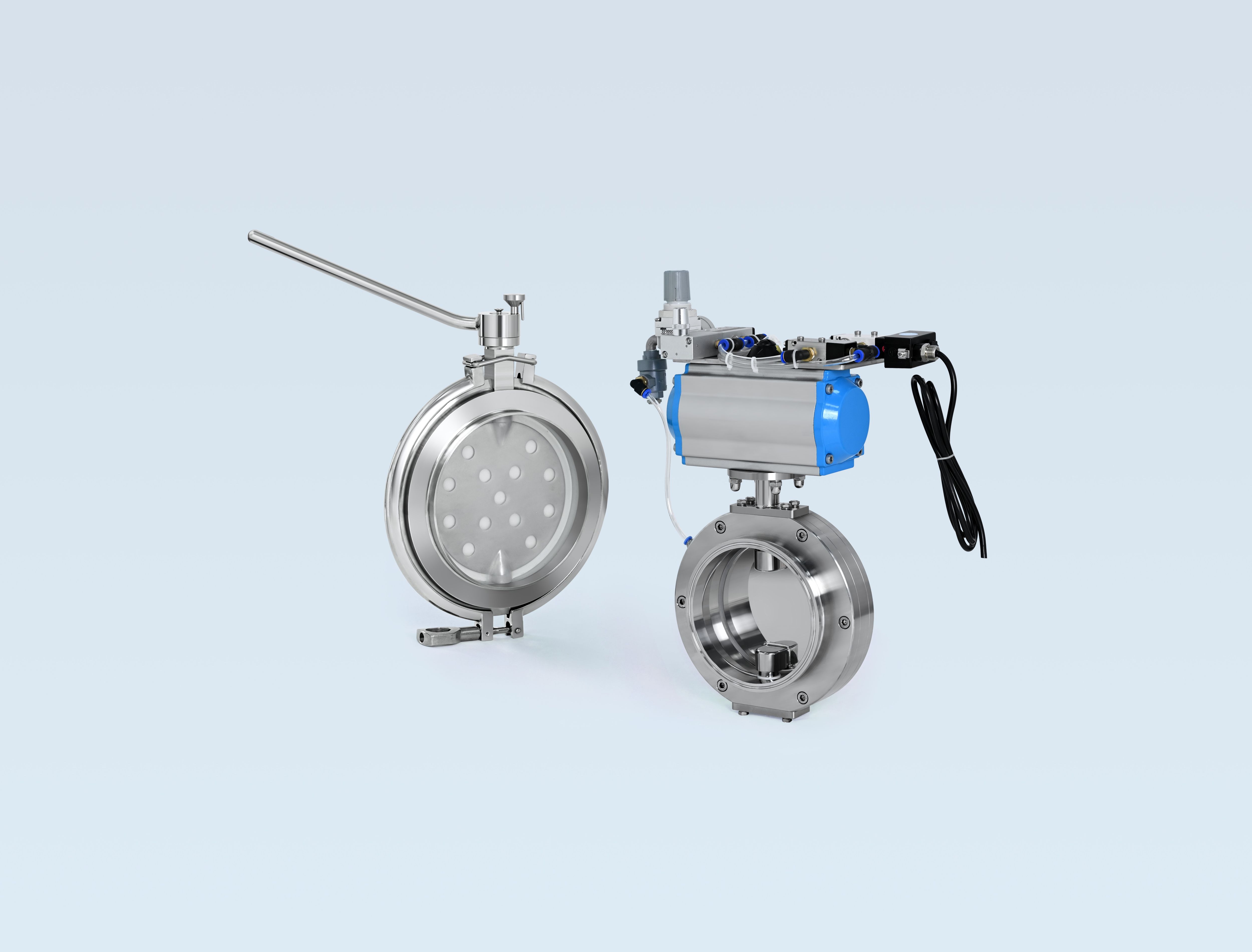
A seal is often judged by its bulk shape, but the real work happens where two surfaces meet. Even a few microns of deviation in flatness or a slight radius mismatched with the groove can open pathways that leak under pressure. Those tiny gaps don't just allow fluid to escape; they create uneven stress along the contact line, which accelerates wear and leads to premature failure in the field.
When engineers talk about the price of a small gap, they aren't only counting lost product or wasted energy. A gap that opens for milliseconds under a pressure spike can cause cavitation damage, emulsify lubricants, or let contaminants wedge into the sealing interface. Over time, the geometry that seemed acceptable on paper becomes a recurring maintenance cost that far exceeds the savings from looser machining tolerances.
The solution usually isn't a harder squeeze, but a smarter contour. Shifting the contact point closer to the pressure side, adding a controlled back angle, or matching the surface roughness to the seal material changes how a gap behaves when the system flexes. In high-cycle applications, this kind of geometry tuning can drop leak rates by an order of magnitude without increasing installation force, turning a microscopic gap into a non-issue.
Flow Path Design Where Smooth Beats Straight
Straight lines often feel like the obvious choice when mapping a user's journey, but they rarely reflect how attention actually moves. Smooth, curved paths give the eye a natural rhythm, letting people wander without feeling forced toward a premature endpoint. This subtle nudge changes the entire tone of an interface, making exploration feel like a guided drift rather than a checklist.
Take a landing page as an example: a rigid vertical stack asks for commitment at every scroll, while a gently arcing layout lets secondary elements breathe around the primary message. The curve delays the hard sell, creating pockets of visual rest that keep users engaged longer. It's not about avoiding clarity, but about replacing friction with flow.
The real advantage shows up in retention. When users don't have to fight the geometry of a page, they invest more energy in the content itself. Smooth paths remove the subtle anxiety of "where am I supposed to look next" and replace it with a quiet confidence that the design already knows the way. That is the difference between a path people follow and one they abandon halfway.
Actuation Speed Without Losing Precision
Fast actuation often tempts engineers to trade away fine positioning for shorter move times, but that compromise isn't always necessary. The trick lies in how the control loop reads feedback during high-velocity travel. Instead of sampling position at a fixed, leisurely interval, a tightly coupled encoder and drive can track trajectory errors every few microseconds, making corrections before inertia pulls the stage off course. This keeps the motion crisp without letting overshoot creep in at the end of the stroke.
Another factor that gets overlooked is the mechanical path between motor and payload. A stiff, low-backlash coupling preserves the commanded motion instead of acting like a spring that stores and releases energy unpredictably. Pair that with jerk-limited acceleration profiles and the system can reach full speed quickly yet settle into position with micrometer-level repeatability. The result is an actuator that moves with urgency but still lands exactly where it's told, cycle after cycle.
Pressure Drop Realities in Day to Day Operation
In real plants, pressure drop rarely matches design sheets. Fouling, partially open valves, or accumulated debris in strainers create extra resistance that operators notice as pump discharge pressure climbing while flow stays stubbornly low. These discrepancies are not trivial; they force equipment to run off its curve and often mask a blockage until it becomes an emergency.
Day-to-day operation means making small corrections based on gauge readings rather than waiting for a scheduled shutdown. A filter that shows a 10 psi increase from baseline might be fine today, but the same 10 psi on a fin-fan cooler during cold weather can signal something else entirely. Experienced technicians learn which pressure drops are normal for their unit, and which ones point to a developing problem.
The real challenge is that pressure drop is never constant. Load changes, ambient temperature swings, and even the position of a manual bypass valve shift the readings throughout a shift. Good operating practice relies on trend lines, not single numbers, because a slow creep over three days tells more than one high reading after a rainstorm.
Maintenance Access That Won't Shut You Down
For equipment that has to keep running while you work on it, the maintenance access points are designed with isolation in mind. You can open the panel, reach the filter, swap a module, or check a connection without tripping a safety interlock that kills the whole line. Dedicated bypass channels and redundant power paths mean maintenance becomes a side task, not a scheduled outage.
The layout places high-wear components behind their own sealed compartments, so a single failure never forces you to take down adjacent systems. Lockable access doors with clear status indicators let technicians work confidently, even in live environments. And because every access point is tool-less or single-tool, routine checks happen in minutes instead of hours.
FAQ
The first thing is always the flow characteristics of the powder. A valve that works for free-flowing granules will fail with cohesive or sticky material. We look at particle size, bulk density, moisture content, and abrasiveness before deciding on anything else.
Sharp transitions and dead corners create places where powder can pack or bridge. We prefer smooth, sloped internal surfaces and avoid cavities where material can sit. Even a small ledge can eventually cause a blockage or cross-contamination.
Powders are often abrasive or corrosive. A stainless steel valve might be fine for food powders, but a mineral powder could wear it out quickly. We specify hardened alloys, coatings, or even ceramic liners depending on the application. The wrong material means frequent replacement and downtime.
Fine powders will find any gap. We use inflatable seals, metal-to-metal seats with tight tolerances, or specialized polymer seals that resist abrasion. For very fine or toxic powders, double-seal arrangements with a purge port are common.
It is about minimizing shear and maintaining a consistent flow path. We avoid sudden expansions or contractions, and for fragile powders we use slow-opening or low-shear designs. Some valves also incorporate internal flow straighteners to keep the mixture homogeneous.
Look for tool-free access to internals, replaceable wear parts, and a design that does not require removing the entire valve from the line. We also recommend valves with self-cleaning or purge options for applications where frequent product changes occur.
A valve that seals perfectly at atmospheric pressure may leak under vacuum or high differential pressure. We evaluate the operating pressure range and test for both directions. For vacuum conveying, we often use valves with specially loaded seals or double-flap designs.
It depends on the range of powders. A single valve can often handle a family of similar materials, but switching from a free-flowing resin to a sticky pigment usually requires a different design. We always ask about the full range of products the line will process.
Conclusion
Material selection in powder valves goes far beyond resisting abrasion. The right alloy or polymer also determines how well the valve copes with fines, moisture, and electrostatic buildup—factors that cause clogging or erratic discharge even when wear life looks acceptable on paper. Equally important is seal geometry: a gap of just a few microns can let fine powder escape, contaminate the surrounding area, or allow air ingress that disturbs flow. Many field failures trace back to seal faces that were perfectly machined but poorly matched to the powder's particle size distribution. Flow path design adds another layer. Smooth internal contours with generous radii consistently outperform straight-through channels that create dead zones or abrupt directional changes, because powder tends to pack and bridge wherever velocity drops.
Actuation speed is often treated as a simple throughput lever, but fast movement without controlled deceleration leads to hammering, particle attrition, and loss of repeatable positioning. The most reliable valves pair quick actuation with damping or servo control to preserve precision. Pressure drop is another daily reality: a valve that looks efficient in a catalog can quietly add enough resistance to destabilize downstream feeding or require extra energy. Operators quickly learn that a low-pressure-drop design keeps product moving predictably across varying line conditions. Finally, maintenance access cannot be an afterthought. Valves that allow seal or seat replacement without removing the body from the line, or that use split housings and quick-release clamps, dramatically reduce downtime and keep production running during routine service.
Contact Us
Contact Person: Ananda
Email: [email protected]
Tel/WhatsApp: 8619016718200
Website: https://www.wzaomi.com